Electrofusion Pipework

Electrofusion Pipework
UPP® pipework utilizes the advanced electrofusion welding process to effectively bond system components including pipework and containment together into one, watertight system.
UL UPP® pipe is offered in 1½", 2", 3", and 4" diameters and a variety of stick and coil sizes.
EN UPP® pipe is offered in 32mm, 50mm, 63mm, 90mm, 110mm, and 160mm diameters and a variety of stick and coil sizes.
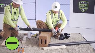
We met up with veteran petroleum equipment contractors for their first UPP® Electrofusion Pipework installation. See for yourself what these experts had to say.

A WATERTIGHT PIPEWORK SYSTEM SOLUTION
With over 30 years of proven performance, UPP® of semi-rigid pipework is the world's first electrofusion pipework system for fuel applications, and remains today, the best-in-class watertight solution for pipework and containment globally.

Electrofusion Welding
At the heart of the UPP® pipework system is the highly efficient electrofusion welding process that connects pipe, fittings, boots and containment to create a seamless direct burial pipework system.

Gemini™ Secondary Containment
Gemini™ double wall fittings are specifically designed to enclose one-piece primary fittings, reducing the number of parts, welds, time, and overall cost.

Versatility
UPP® pipe is suitable for all fueling applications including product lines, vent lines, vapor lines, and above and below grade environments.

UPP® semi-rigid pipework utilizes the advanced electrofusion welder and welding process to effectively bond system components together into one, leak-proof system.

Fast Welding Process
After connecting a welder and its leads to a fitting, the installer presses a single button to initiate the welding process.

A Smart Welder
The welder calculates the exact settings needed regardless of pipe diameter, component, or ambient temperature.

Easy for the Installer
There is nothing for the installer to input, no language barrier to overcome, with the same process for all types of pipes, fittings, and entry boots.

In both of the polyethylene and fiberglass sump sealing processes, the boot, sump, and pipework become one solid structure, creating a watertight system.

Remove Leak Paths
The boot, sump and pipework actually become one solid structure, creating a 100% watertight system, free of mechanical seals and potential leak paths.

Polyethylene Connections
Entry boots directly weld to polyethylene sumps using the electrofusion welding process to create one, solid structure.

Fiberglass Connections
A polyethylene sleeve is over-molded onto a metallic ring that is fiberglassed to the sump to create a watertight joint.

Patented UPP® Gemini Secondary Containment fittings feature a two-piece design that can be fully welded and tested before closing the secondary, something no other brand can offer.

Less Fittings, More Savings
Designed to enclose standard one-piece primary fittings, thus drastically reducing the number of necessary parts, welds, time and overall cost.

Weld, Then Test
Avoid discovering a breach in the system after the secondary has been welded, saving significant installation time and cost.

Complete Confidence
With Gemini's integrity testing capabilities, you get a level of confidence which installers and end users have yet to experience until now.

UPP® pipework provides a non-corrosive alternative to steel & fiberglass with additional installation and performance benefits.
Greater Flexiblity
UPP® pipework is highly flexible unlike steel and fiberglass - it’s also structurally resistant to seismic activity, backfill, and traffic during install.
Non-Corrosive
Corrosion in steel piping can be caused by aggressive soils and can lead to large scale issues and joint failures – UPP® pipe and fittings simply cannot corrode.
Low Maintenance
With steel, ground movement, water hammer and friction losses can create ongoing maintenance costs after installation is complete, costs you can avoid with UPP®.
From cleaning and prepping the components, to executing the weld, the simple 8-step electrofusion welding process yields watertight connections throughout the pipework system.
UPP® UL-971 Standard Primary Pipe
- Pipe outer layer: High Density Polyethylene (HDPE) grade PE100
- Pipe liner layer: Ethylene vinyl alcohol (EVOH) resin liner
- Pipe intermediate layer: Tie-layer which permanently bonds HDPE outer layer to EVOH resin liner layer
- Temperature rating: -22 °F to 122 °F
- Primary pipe pressure rating: 90 Psi
- Secondary pipe pressure rating: 50 Psi
- 1½" and 2” double wall pipe bend radius: 3'3"
- 3" and 4" double wall pipe bend radius: 13'2"
- 2" single wall vent/vapor pipe bend radius: 3'3"
- 3" single wall vent/vapor pipe bend radius: 9'10"
Fuel Compatibility
- UL-971 approved for fuels including:
- Motor vehicle fuels typically found in consumer dispensing facilities like gasoline or diesel including blended fuels with maximum 15% MTBE, 15% Methanol or 30% Ethanol.
- Concentrated fuels such as alternate un-blended fuels containing up to 100% concentrations of Toluene, Methanol or Ethanol.
- High blend fuels with higher than normal gasoline blends with maximum 50% Methanol or 50% Ethanol.
- Aviation and marine specialty fuels containing up to 100% kerosene or leaded gasoline.
- Michigan, Wisconsin, and Florida EQ-816 leaded gasoline
Ethanol Blends Compatibility
- High-blend Ethanol, with ethanol/gasoline blends between 51%-83% (E51-E83) - commercially known as "E-85"
Biodiesel Compatibility
- Biodiesel up to 5% (B5)
- Biodiesel up to 20% (B20)
- Biodiesel at 97% - 100% (B99 / B100)
- All ASTM defined biofuel blends
UPP® EN14125:2013 Standard Primary Pipe
- Material: PE100 with EVOH resin barrier
- Primary pressure rating (bar/psi): 10/145
- Primary colour: Black with two clusters of four green stripes, clear inner liner
- Temperature rating: Class T1 Rating (EN14125) -40 °C to 50 °C
- Primary vacuum rating (-bar/"Hg): -0.9/-26.6
UPP® EN14125:2013 Standard Fill Pipe
- Material: PE100 with EVOH resin barrier
- Primary pressure rating (bar/psi): 6/87
- Primary colour: Black with two clusters of four green stripes, clear inner liner
- Temperature rating: Class T1 Rating (EN14125) -40 °C to 50 °C
UPP® EN14125:2013 Standard Coaxial (Secondary) Pipe
- Material: PE100 with EVOH resin barrier
- Primary pressure rating (bar/psi): 10/145
- Primary colour: Black with two clusters of four green stripes, clear inner liner
- Secondary colour: Black with six green stripes
- Secondary pressure rating (bar/psi): 5/72
- Temperature rating: Class T1 Rating (EN14125) -40 °C to 50 °C
- Primary vacuum rating (-bar/"Hg): -0.9/-26.6
- Secondary vacuum rating (-bar/"Hg): -0.6/-17.8
UPP® EN14125:2013 Standard Secondary Sleeve
- Material: PE100
- Secondary pressure rating (bar/psi): 5/72
- Primary colour: Black with six green stripes
- Temperature rating: Class T1 Rating (EN14125) -40 °C to 50 °C
- Secondary vacuum rating (-bar/"Hg): -0.6/-17.8
UPP® UL-971 Single Wall Pipe
| Model Number | Description |
|---|---|
| 001-063-019VE | 2" single wall pipe |
UPP® UL-971 Double Wall Pipe
| Model Number | Description |
|---|---|
| 001-063-050-028PSE | 1½" double wall pipe |
| 001-063-050-033PSE | 1½" double wall pipe |
| 001-063-050-165PSE | 1½" double wall pipe |
| 001-075-063-028PSE | 2" double wall pipe |
| 001-075-063-033PSE | 2" double wall pipe |
| 001-075-063-038PSE | 2" double wall pipe |
| 001-075-063-100PSE | 2" double wall pipe |
| 001-075-063-165PSE | 2" double wall pipe |
| 001-110-090-019PSE | 3" double wall pipe |
UPP® EN14125:2013 Standard Primary Pipe
| Model Number | Description |
|---|---|
| 001-032-100-E | UPP® Extra Pipe 32 mm Coil 100 m |
| 001-050-006-E | UPP® Extra Pipe 50 mm L=5.8 m |
| 001-050-050-E | UPP® Extra Pipe 50 mm Coil 50 m |
| 001-050-100-E | UPP® Extra Pipe 50 mm Coil 100 m |
| 001-063-006-E | UPP® Extra Pipe 63 mm L=5.8 m |
| 001-063-008-E | UPP® Extra Pipe 63 mm L=8 m |
| 001-063-100-E | UPP® Extra Pipe 63 mm Coil=100 m |
| 001-090-006-E | UPP® Extra Pipe 90 mm L=5.8 m |
| 001-090-050-E |
UPP® Extra Pipe 90 mm Coil 50 m |
| 001-110-006-E | UPP® Extra Pipe 110 mm L=5.8 m |
UPP® EN14125:2013 Standard Fill Pipe
| Model Number | Description |
|---|---|
| 001-110-006-FILL-E | UPP® Extra FILL Pipe 110 mm L=5.8 m |
UPP® EN14125:2013 Standard Coaxial (Secondary) Pipe
| Model Number | Description |
|---|---|
| 001-040-032-050-E | UPP® Extra 32 mm Coaxial Coil 50 m |
| 001-040-032-100-E | UPP® Extra 32 mm Coaxial Coil 100 m |
| 001-063-050-030-E | UPP® Extra Coaxial Pipe 50 mm Coil 30 m |
| 001-063-050-100-E | UPP® Extra Coaxial Pipe 50 mm Coil 100 m |
| 001-075-063-010-E | UPP® Extra Coaxial Pipe 63 mm L=10M |
| 001-075-063-030-E | UPP® Extra Coaxial Pipe 63 mm Coil 30M |
| 001-075-063-050-E | UPP® Extra Coaxial Pipe 63 mm Coil 50 M |
| 001-125-110-030-E | UPP® Extra Coaxial Pipe 110 mm Coil 30 M |
| 001-125-110-050-E | UPP® Extra Coaxial Pipe 110 mm Coil 50 M |
UPP® EN14125:2013 Standard Secondary Sleeve
| Model Number | Description |
|---|---|
| 000-063-006-SC-E | UPP® Secondary Pipe 63 mm L=5.8 m |
| 000-075-006-SC-E | UPP® Secondary Pipe 75 mm L=5.8 m |
| 000-075-008-SC-E | UPP® Secondary Pipe 75 mm L=8 m |
| 000-110-006-SC-E | UPP® Secondary Pipe 110 mm L=5.8 m |
| 000-125-006-SC-E | SC 125 mm Outer Sleeve: 5.8 m stick length |
Featured


Brochures
| Title | Type | Size | |
|---|---|---|---|
 |
FFS-0234 (EN) UPP Semi Rigid Pipework System Datasheet.pdf | 3.85 MB | |
 |
FFS-0305 (EN) Double Wall Termination Fittings Brochure.pdf | 4.56 MB | |
 |
FFS-0536 (EN) DEF Pipework Systems Brochure.pdf | 0.99 MB | |
 |
FFS-0720 UPP Pipework System.pdf | 2.27 MB | |
 |
FFS-0164 (UL) UPP Semi-Rigid Pipework System Datasheet.pdf | 3.67 MB | |
 |
FFS-0507 EVOH Lined Pipework Brochure.pdf | 0.5 MB | |
 |
FFS-0509 Gemini Fittings Brochure.pdf | 0.81 MB | |
 |
FFS-0508 Electrofusion Entry Seals Brochure.pdf | 0.73 MB | |
 |
FFS-0535 (UL) DEF Pipework Systems Brochure.pdf | 0.97 MB |
Catalogs
| Title | Type | Size | |
|---|---|---|---|
 |
FFS-0807 (EN) Product Catalogue.pdf | 153.77 MB | |
 |
FFS-0367 (UL) Site Starters Ordering Guide.pdf | 64.42 MB | |
 |
FFS-1028 2025 UL Ordering Catalog.pdf | 95.28 MB |